The Game Console
I thought it would be cool to design my own handheld console for this game, and despite some initial frustrations it has been fun to develop. Some neat aspects of this design:
- There is a pop out button panel on the left side with buttons for starting my game directly, for starting a media center to play locally stored videos, and two others for shutting the device off and to turn the wireless interface up or down
- Not only is there a battery pack so the game console is portable, but the battery also acts as a UPS for seamless transitions between powering the console over USB-C and the battery
- Audio can be routed through two external speakers or to a 3.5mm audio jack using a manual 3-Pos DPDT switch
- Volume control is achieved using a dual-gang 5k potentiometer and a couple of gears
- The screen is 7”, much larger than your typical handheld Retropie case from Adafruit allows for (no hate on them, I also have a case like this)
- There is a removable SD card in a pop out panel on the right side which has the RetroPie OS and some games installed (there were issues getting it installed as an application)
- A fan to keep the computer cool
- Neat assembly / disassembly that requires no unsoldering to get to the guts of the game console
- You can swap out an analog joystick with a d-pad in under a minute if you want
I cover the game console’s development more in depth on my personal website here. That discusses everything from assembling the hardware to configuring the software. If you want to see how the game console was developed I’ve recorded those on my YouTube channel. To give a brief overview, the game console can be divided into two main categories - the 3d-printed case and the electronic components inside:
3d model
If you want to view these all in a single webpage I have put them on display here. Otherwise you can view and download them from my Skethfab account or from this Github repository. There are 71 total pieces that I needed to design and print off, so a lot of effort went into this design.
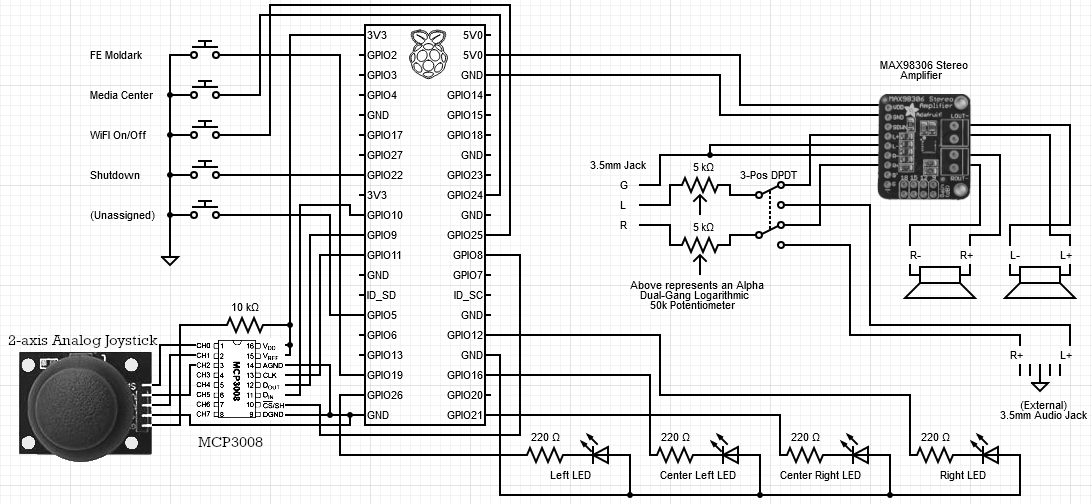
Circuit Diagram
This is what the final circuit diagram for the game console looks like:

Electronic Components
*Goes without saying but none of this is sponsored, this is just where I happened to source the parts for this project from. If you can find these pieces cheaper elsewhere, go for it.
- 1x Raspberry Pi 4 Model B (4 GB Ram)
- 1x Waveshare UPS HAT (B) and 2x 18650 batteries
- 1x 7” LCD
- 1x Stereo 3.7W Class D Audio Amplifier - MAX98306
- 1x Alpha Dual-Gang 16mm Right-angle PC Mount - 5K Audio
- 4x 220 Ohm and 1x 10K Ohm Resistors
- 4x Diffused 3mm LEDs
- 1x Analog 2-axis joystick (This one should work, I got mine from a sensor module kit 4+ years ago)
- 1x MCP3008 Analog-to-Digital converter
- 2x PiGrrl Zero Custom Gamepad PCB
- A mixture of these, these and these buttons depending on purpose and preference (overall 13 buttons are needed)
- 3x speakers (yes, three)
- 1x 3.5mm audio jack breakout board
- 1x Female GPIO Header and 1x Male GPIO Header
- 3x Male and 3x Female USB Type A breakouts like the ones seen in this kit
- 1x SPST or SPDT switch
- 1x Fan
- 2x A1 Ribbon FPV Connector and 1x FFC Ribbon Cable 5cm
- 1x 3-Pos 6 pin DPDT switch that looks something like this
- 1x USB joystick (this one should work, I got mine in 2018 so it’s no longer available), and you’ll need to rip the guts out of this thing
- 1x 90 degree USB-C right angle adapter (option 5)
- Wire ranging from 30 AWG for the buttons / LEDs, to 22 AWG for the speakers and some common power lines, to 16 gauge wire for the 5V 3A lines between the UPS and Pi board
- Solder, soldering iron, heat shrink tubing, perfboards / breadboards, wire cutters, etc.
- 2x plastic gears, 3x springs and superglue (reference video for more on this)